
Circuito do Injetor DTC P0201 / Aberto - (Cilindro 1) |
Circuito do Injetor DTC P0202 / Aberto - (Cilindro 2) |
Circuito do Injetor DTC P0203 / Aberto - (Cilindro 3) |
Circuito do Injetor DTC P0204 / Aberto - (Cilindro 4) |
Desempenho do circuito do driver do injetor de combust�vel DTC P062D No. 1 |
|
Padr�o de unidade de detec��o DTC |
Condi��o de Detec��o DTC |
�rea de problemas |
|
Inativo por 5 segundos |
Aberto ou curto no circuito do
injetor ocorre um certo n�mero de vezes (no m�ximo aproximadamente 0,5
segundos). (1 l�gica de detec��o de disparo) |
|
|
Padr�o de unidade de detec��o DTC |
Condi��o de Detec��o DTC |
�rea de problemas |
|
Inativo por 5 segundos |
Inconsist�ncia nas formas de onda
da inje��o entre o driver do injetor e o ECM enquanto o motor estiver em
funcionamento um certo n�mero de vezes (no m�ximo aproximadamente 0,5
segundos). (1 l�gica de detec��o de disparo) |
|

| 1. VERIFIQUE A CONDI��O DO MOTOR |
Verifique as condi��es de partida do
motor.
|
Resultado |
Prossiga para |
|
O mecanismo n�o inicia * 1 |
UMA |
|
O motor arranca, mas a marcha
lenta � dif�cil * 2 |
B |
|
Exceto acima |
C |
|
|
||||
|
|
||||
| UMA |
|
|
|
|
| 2. INSPECIONE ECM |
 |
Verifique a forma de onda dos
conectores do ECM usando um oscilosc�pio.
|
Conex�o do testador |
Condi��o |
Condi��o especificada |
|
E29-21 (# 1) - E28-6 (E1) |
Cranking |
A forma de onda correta �
como mostrado |
|
E29-22 (# 2) - E28-6 (E1) |
Cranking |
A forma de onda correta �
como mostrado |
|
E29-23 (# 3) - E28-6 (E1) |
Cranking |
A forma de onda correta �
como mostrado |
|
E29-24 (# 4) - E28-6 (E1) |
Cranking |
A forma de onda correta �
como mostrado |
|
*uma |
Componente com chicote
conectado (ECM) |
|
|
||||
| Est� bem |
|
|
|
|
| 3. VERIFIQUE A FONTE DE ENERGIA DO CONTROLADOR DO INJETOR DA TENS�O |
 |
Desconecte os conectores do driver do
injetor.
Me�a a tens�o de acordo com os valores
na tabela abaixo.
|
Conex�o do testador |
Condi��o do interruptor |
Condi��o especificada |
|
I17-2 (+ B) - I17-4 (GND) |
Interruptor de igni��o |
11 a 14 V |
|
*uma |
Vista frontal do conector da
fia��o (ao driver do injetor) |
Reconnect the injector driver connectors.
|
|
||||
| OK |
|
|
|
|
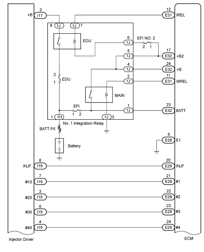
| 4.CHECK HARNESS AND CONNECTOR (INJECTOR DRIVER - ECM) |
Disconnect the injector driver connector.
Disconnect the ECM connector.
Measure the resistance according to the value(s) in the table below.
|
Tester Connection |
Condition |
Specified Condition |
|
I19-7 (#10) - E29-21 (#1) |
Always |
Below 1 Ω |
|
I19-3 (#20) - E29-22 (#2) |
Always |
Below 1 Ω |
|
I19-6 (#30) - E29-23 (#3) |
Always |
Below 1 Ω |
|
I19-4 (#40) - E29-24 (#4) |
Always |
Below 1 Ω |
|
I19-8 (INJF) - E29-20 (INJF) |
Always |
Below 1 Ω |
|
I19-7 (#10) or E29-21 (#1) - Body ground |
Always |
10 kΩ or higher |
|
I19-3 (#20) or E29-22 (#2) - Body ground |
Always |
10 kΩ or higher |
|
I19-6 (#30) or E29-23 (#3) - Body ground |
Always |
10 kΩ or higher |
|
I19-4 (#40) or E29-24 (#4) - Body ground |
Always |
10 kΩ or higher |
|
I19-8 (INJF) or E29-20 (INJF) - Body ground |
Always |
10 kΩ or higher |
Reconnect the injector driver connector.
Reconnect the ECM connector.
|
|
||||
| OK |
|
|
|
|
| 5.REPLACE INJECTOR DRIVER |
Replace the injector driver (Click
here).
|
|
||||
| 6.CHECK WHETHER DTC OUTPUT RECURS |
Connect the GTS to the DLC3.
Turn the ignition switch to ON and turn the GTS on.
Clear the DTCs (Click
here).
Turn the ignition switch off for 30 seconds.
Start the engine and idle it for 30 seconds.
Enter the following menus: Powertrain / Engine / Trouble Codes.
Check the DTCs output on the GTS.
| NEXT |
|
|
|
|
| 7.INSPECT INJECTOR DRIVER |
 |
Disconnect the injector assembly connectors for all cylinders.
Start the engine.
Check the waveform of the injector assembly connectors using an oscilloscope.
|
Tester Connection |
Condition |
Specified Condition |
|
F31-3 (#1) - F31-6 (#10) |
Cranking |
Voltage increases by 50 V or more |
|
F32-3 (#2) - F32-6 (#20) |
Cranking |
Voltage increases by 50 V or more |
|
F33-3 (#3) - F33-6 (#30) |
Cranking |
Voltage increases by 50 V or more |
|
F34-3 (#4) - F34-6 (#40) |
Cranking |
Voltage increases by 50 V or more |
|
*a |
Front view of wire harness connector (to Fuel Injector) |
|
|
||||
| OK |
|
|
|
|
| 8.REPLACE INJECTOR ASSEMBLY (RELEVANT CYLINDER) |
Replace the injector assembly of the cylinder relevant to the DTC (Click
here).
| NEXT |
|
|
|
|
| 9.BLEED AIR FROM FUEL SYSTEM |
Bleed the air from the fuel system (Click
here).
|
|
||||
| 10.REPLACE ECM |
Replace the ECM (Click
here).
|
|
||||
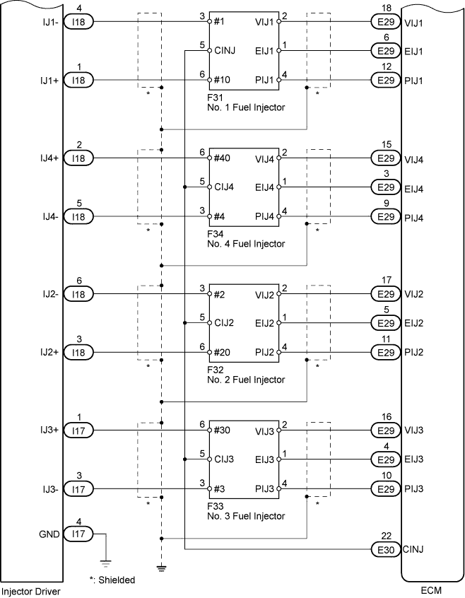
| 11.CHECK HARNESS AND CONNECTOR (INJECTOR ASSEMBLY - INJECTOR DRIVER) |
Disconnect the injector assembly connectors.
Disconnect the injector driver connectors.
Measure the resistance according to the value(s) in the table below.
|
Tester Connection |
Condition |
Specified Condition |
|
F31-6 (#10) - I18-1 (IJ1+) |
Always |
Below 1 Ω |
|
F31-3 (#1) - I18-4 (IJ1-) |
Always |
Below 1 Ω |
|
F32-6 (#20) - I18-3 (IJ2+) |
Always |
Below 1 Ω |
|
F32-3 (#2) - I18-6 (IJ2-) |
Always |
Below 1 Ω |
|
F33-6 (#30) - I17-1 (IJ3+) |
Always |
Below 1 Ω |
|
F33-3 (#3) - I17-3 (IJ3-) |
Always |
Below 1 Ω |
|
F34-6 (#40) - I18-2 (IJ4+) |
Always |
Below 1 Ω |
|
F34-3 (#4) - I18-5 (IJ4-) |
Always |
Below 1 Ω |
|
F31-6 (#10) or I18-1 (IJ1+) - Body ground |
Always |
10 kΩ or higher |
|
F31-3 (#1) or I18-4 (IJ1-) - Body ground |
Always |
10 kΩ or higher |
|
F32-6 (#20) or I18-3 (IJ2+) - Body ground |
Always |
10 kΩ or higher |
|
F32-3 (#2) or I18-6 (IJ2-) - Body ground |
Always |
10 kΩ or higher |
|
F33-6 (# 30) ou I17-1 (IJ3
+) - Massa corporal |
Sempre |
10 kΩ ou superior |
|
F33-3 (# 3) ou I17-3
(IJ3-) - Massa corporal |
Sempre |
10 kΩ ou superior |
|
F34-6 (# 40) ou I18-2 (IJ4
+) - Massa corporal |
Sempre |
10 kΩ ou superior |
|
F34-3 (# 4) ou I18-5
(IJ4-) - Massa corporal |
Sempre |
10 kΩ ou superior |
Reconecte os conectores do conjunto do
injetor.
Reconecte os conectores do driver do
injetor.
|
|
||||
| Est� bem |
|
|
|
|
| 12. SUBSTITUIR O CONTROLADOR DO INJETOR |
Substitua o driver do injetor ( clique
aqui ).
|
|
||||
| 13.REPARAR OU SUBSTITUIR ARN�S OU CONECTOR |
Repare ou substitua o chicote ou o
conector.
| PR�XIMO |
|
|
|
|
| 14..Confirmar se o malfuncionamento foi reparado com sucesso |
Conecte o GTS ao DLC3.
Limpe os DTCs ( Clique
aqui ).
Desligue a igni��o por 30 segundos ou
mais.
Ligue o motor e mantenha-o em marcha
lenta por 5 segundos.
Digite os seguintes menus: Powertrain
/ Engine / Trouble Codes.
Confirme se o DTC n�o � exibido
novamente.
| PR�XIMO |
|
|
|
|
|
|
|
||